A Solar Inverter is the control center between photovoltaic panels and usable electricity. It converts the panels’ direct current into alternating current for homes, businesses, and the grid. It also tracks maximum power points, manages voltage, and monitors system performance. Some models include battery control, backup functions, and rapid shutdown protection.
The market is expanding quickly. The International Energy Agency reported that solar photovoltaic additions exceeded 400 gigawatts globally in 2023. The IEA Photovoltaic Power Systems Programme also identified 2023 as another record year for worldwide PV deployment. Wood Mackenzie’s inverter research shows how rapidly shipments and competition are growing across residential, commercial, and utility-scale projects. These numbers matter because every new panel array needs reliable power conversion.
As SMA founder Günther Cramer reportedly put it, “The inverter is the heart of a photovoltaic system.” The comparison is practical. A rooftop may look quiet, but the inverter continuously adjusts electrical output inside its enclosure. Fans, heat sinks, firmware, and sensors work together there.
Still, calling it the “heart” is incomplete. Panels produce energy, while the inverter determines how safely and efficiently that energy travels. A poor installation can reduce performance, even with excellent equipment. Temperature, shading, grid conditions, and maintenance all influence results. This guide explains the technology clearly, while acknowledging one uncomfortable truth: inverter ratings alone cannot predict real-world performance.
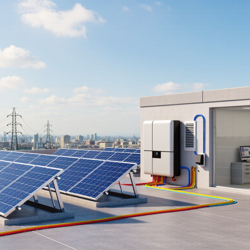
A solar inverter is the PV system’s DC-to-AC power converter. Solar modules produce direct current (DC), while household appliances and utility grids use alternating current (AC). The inverter changes the electrical form and helps manage usable panel power. It also uses maximum power point tracking (MPPT) to adjust voltage and current as sunlight and module temperature shift. Small changes matter. NREL’s PVWatts Version 8 documentation uses 96% as its default inverter efficiency. That figure is a modeling assumption, not a guaranteed field result; heat, wiring, shading, and system sizing can affect actual output.
Inside the inverter, electronic switches rapidly shape DC into AC, while control circuits regulate the output. The inverter also synchronizes its voltage and frequency with the grid. In a typical installation, DC cables run from the panels to the inverter, and AC cables carry converted power to the building’s electrical panel. A monitoring screen may show DC input and AC output side by side. The difference can reveal conversion losses, though it does not explain every loss in the system. It is tempting to treat one efficiency percentage as the whole story. That would be misleading: operating conditions change, and real systems rarely sit at one perfect point.
Photovoltaic cells turn sunlight into direct-current electricity through the behavior of semiconductor materials. When light reaches a cell, its photons transfer energy to electrons, freeing some to move. An internal electric field guides that movement, creating a voltage between the cell’s contacts. Connect the cell to a circuit, and current can flow. It is not sunlight flowing through a wire.
A single cell produces only a small voltage, so many cells are wired together inside a module. Modules can then be connected in series to raise the system voltage or in parallel to increase current. The resulting DC power travels along conductors to the inverter. In many systems, the inverter tracks the cells’ changing output to find an operating point that yields useful power. Small shifts matter.
Sunlight, cell temperature, and shading all affect that output. A passing cloud may reduce current; hot cells can produce less voltage, even on a bright day. The inverter must work within the array’s electrical limits, which depend on how its modules are wired. Real arrays are less tidy than diagrams suggest. A narrow strip of shade across one module can affect a connected string, though the impact varies with the system design. Checking module specifications and installation measurements helps explain what DC power the inverter can actually receive.
| Stage or Component | What Happens | Typical Electrical Characteristics | How It Relates to the Inverter |
|---|---|---|---|
| Photovoltaic cell | Semiconductor material absorbs light and creates electrical charge carriers, producing direct current (DC). | A silicon cell commonly operates at roughly 0.5–0.6 V under load; current depends on cell area, sunlight, and temperature. | Individual cells produce low voltage, so many cells are connected together to form a useful DC source. |
| Solar module | Cells connected in series add their voltages; the module’s output varies with sunlight and operating temperature. | Many conventional modules have a maximum-power operating voltage in the tens of volts, often around 30–50 V. | The module supplies DC power through its output cables to the array wiring and inverter input. |
| PV array and wiring | Modules may be connected in series to increase voltage or in parallel to increase current. | For series-connected modules, voltages add while current remains approximately the same. For parallel strings, currents add while voltage remains approximately the same. | The array must remain within the inverter’s specified DC voltage and current limits. |
| Maximum power point tracking (MPPT) | The inverter adjusts the array’s operating voltage and current to seek the point where their product—power—is greatest. | The maximum power point changes with irradiance, module temperature, and other operating conditions. | MPPT helps the inverter draw available DC power efficiently; its operating range is specific to the inverter model. |
| Inverter power conversion | Power electronics switch the DC input at high frequency and shape it into alternating current (AC). | Conversion efficiency is high in modern equipment but varies with load, temperature, and design; some energy is lost as heat. | The inverter converts the PV array’s variable DC output into AC suitable for the intended electrical system. |
| AC output and grid connection | A grid-connected inverter synchronizes its AC output with the grid’s voltage and frequency. | AC voltage and frequency depend on the local electrical system; common nominal frequencies include 50 Hz and 60 Hz. | The AC power can supply compatible building loads or, where permitted and configured, flow to the grid. Grid-connected systems also use protective functions such as anti-islanding. |
| Illustrative series-string example | Ten modules, each operating at 40 V and 10 A, are connected in series at the stated operating point. | Array voltage: 10 × 40 V = 400 V DC. Current: approximately 10 A. DC power: 400 V × 10 A = 4,000 W. | This simplified example illustrates DC input power before conversion losses; actual values change with conditions and system design. |
A solar inverter converts a panel array’s direct-current electricity into alternating current for a building or the grid. Its MPPT control continually adjusts the panels’ operating voltage and current, seeking the point where their product is greatest. Think of a partly cloudy roof: sunlight changes, and the best operating point can shift with it. The inverter keeps adjusting. Small changes matter.
The 95%–99% figure usually describes inverter conversion efficiency, not MPPT tracking efficiency. NREL’s PVWatts model assumes 96% inverter efficiency; it is a modeling default, not a promise for every system. Sandia National Laboratories’ grid-connected inverter performance model likewise accounts for operating conditions, including power level and DC voltage. In practice, heat, shade, wiring losses, and low output can all affect delivered energy. A sunny-day reading alone can mislead.
MPPT helps the array supply usable power near its changing maximum, but it cannot create energy that the panels do not receive. Shaded modules may also respond differently depending on the system design. That detail is easy to overlook. Real-world performance is less tidy than a single efficiency number.
A solar inverter turns the panels’ direct current into alternating current by rapidly switching electronic components. It then shapes the output into a smooth AC waveform. A control system tracks the panels’ maximum power point, adjusting voltage and current as sunlight changes. NREL’s 2024 Annual Technology Baseline uses 98% as an inverter-efficiency assumption for utility-scale solar. That is a model input, not a guarantee for every installation. Heat, shading, and equipment loading can change real-world performance. Small losses matter.
To work with the grid, the inverter monitors its voltage, frequency, and phase, then synchronizes its AC output accordingly. Filters help reduce unwanted electrical ripple, while control circuits respond to changing grid conditions. Grid compatibility is more than matching a voltage number. The inverter must also stop exporting power if the grid supply fails, protecting workers and equipment. IEA PVPS reported more than 1.2 terawatts of installed solar capacity worldwide by the end of 2022 in Trends in Photovoltaic Applications 2023. At that scale, careful commissioning matters. A setting that looks minor on a screen can affect output or reliability. The details deserve a second look.
A solar inverter converts the panels’ direct current (DC) into alternating current (AC) for building loads or the grid. In large arrays, panel strings may operate at 1,000–1,500 V DC, reducing current and cable losses for a given power. That voltage is on the array side; it is not the voltage supplied to household outlets. Cold weather can raise a string’s open-circuit voltage, so designers check the panel count against the inverter’s limits. Small detail, big consequence.
Inside the inverter, switching components shape DC into AC, while sensors track voltage, frequency, and output quality. Grid standards vary by location and connection type. They set requirements for synchronization and responses to abnormal conditions. If the grid fails, anti-islanding controls stop the inverter from feeding power into lines that may be under repair. Some systems must also remain connected during brief disturbances. The exact settings depend on approved local requirements, not guesswork.
Safety controls matter beyond software. Disconnects, overcurrent protection, grounding, and insulation monitoring help manage faults and maintenance risks. High-voltage DC can sustain an arc, so opening a switch does not make every conductor harmless. Technicians verify isolation and test with equipment rated for the system voltage. A neat wiring diagram can still miss a changed string length or a damaged connector. Site checks matter.
It converts the panels’ direct current into alternating current for a home or grid. It also helps manage panel output.
It adjusts panel voltage and current as sunlight and temperature change. Think of clouds crossing a roof. The best operating point can shift.
No. That range usually refers to inverter conversion efficiency, not a guaranteed result. Heat, shade, wiring, and equipment loading affect output.
Conversion losses can explain part of the difference. Wiring and other system losses may contribute too. One screen cannot show everything.
It monitors grid voltage, frequency, and phase, then synchronizes its AC output. Matching one number is not enough.
A grid-connected inverter must stop exporting power during an outage. This helps protect workers and equipment. Small detail, important.
No. It can adjust how the array operates, but it cannot replace sunlight the panels never receive. Shaded modules may behave differently.
Not really. Conditions change throughout the day, so one figure can be too neat. I’d check readings over time.
A Solar Inverter is the power converter at the heart of a photovoltaic system. Solar cells generate direct current (DC) electricity when exposed to sunlight, but household appliances and the electricity grid generally use alternating current (AC). The inverter transforms the panels’ DC output into usable AC power, helping solar energy serve everyday electrical needs.
To capture as much energy as possible as sunlight and operating conditions change, the inverter uses maximum power point tracking (MPPT) to adjust how it draws power from the panels. Modern inverters can typically operate at about 95%–99% efficiency, though actual performance varies. In larger systems, equipment may handle DC voltages around 1,000–1,500 volts and must produce electricity that matches grid requirements. Monitoring functions and safety controls help manage voltage, detect abnormal conditions, and support reliable operation from the panels through to the connected electrical system.

Wemax Power